The process
From a sketch to a cabinet measured in a chamber: what has been done, in order, and what remains.
01
The idea
Opus I starts from a concrete question: what loudspeaker can be built today by applying what the technical literature has established about cabinets, diffraction and listener preference, without the constraints of an assembly line. The first sketch already fixes the section with a flat front and a curved back.
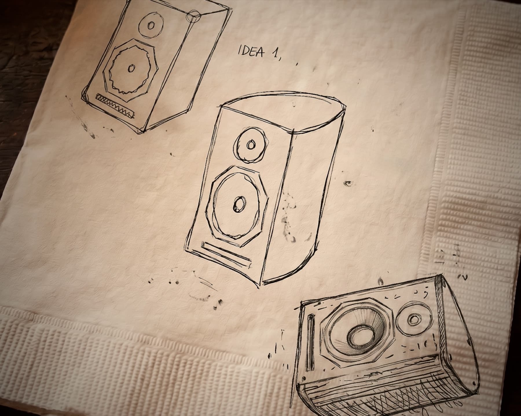
Synthetic imageThe first sketches of the silhouette. Synthetic image based on the original drawings. 02
The design
The cabinet is modelled as a parametric solid: every dimension lives in one file, and from there come the 3D model, the cutting set and the check of volume and tuning. The current version is v11; every revision is noted with its reason.
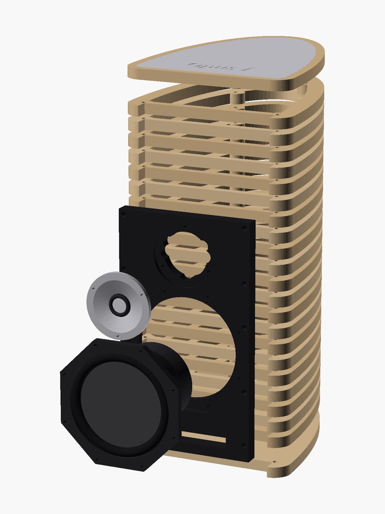
Synthetic imageExploded view of the v11 model. 03
The cutting
The 23 layers, the baffle and the terminal plate are CNC-cut in a local workshop from the files the model generates. No drawing is edited by hand.
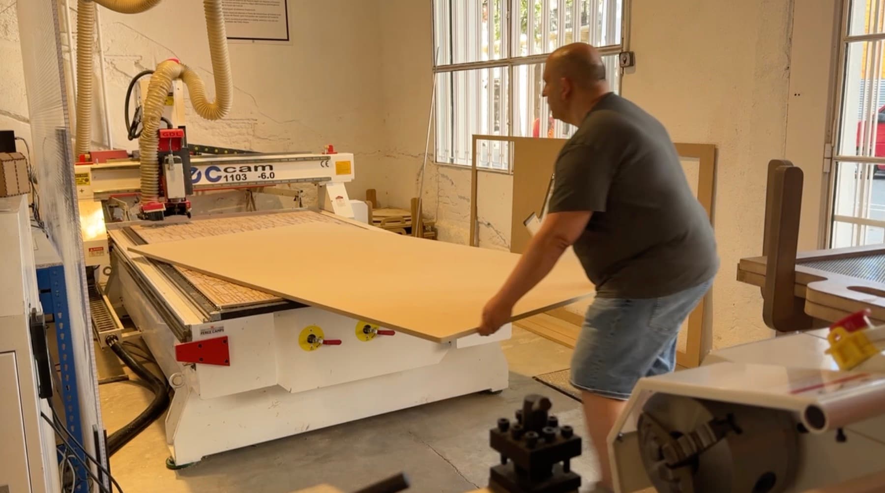
Process photographThe MDF board goes onto the workshop's CNC router. 04
The assembly
The layers are stacked on the threaded rods, compressed, and the baffle is glued on. The terminal plate goes on the back. On the prototype the woofer recess and the screw length were fine-tuned: small adjustments that are noted and fed back into the model.
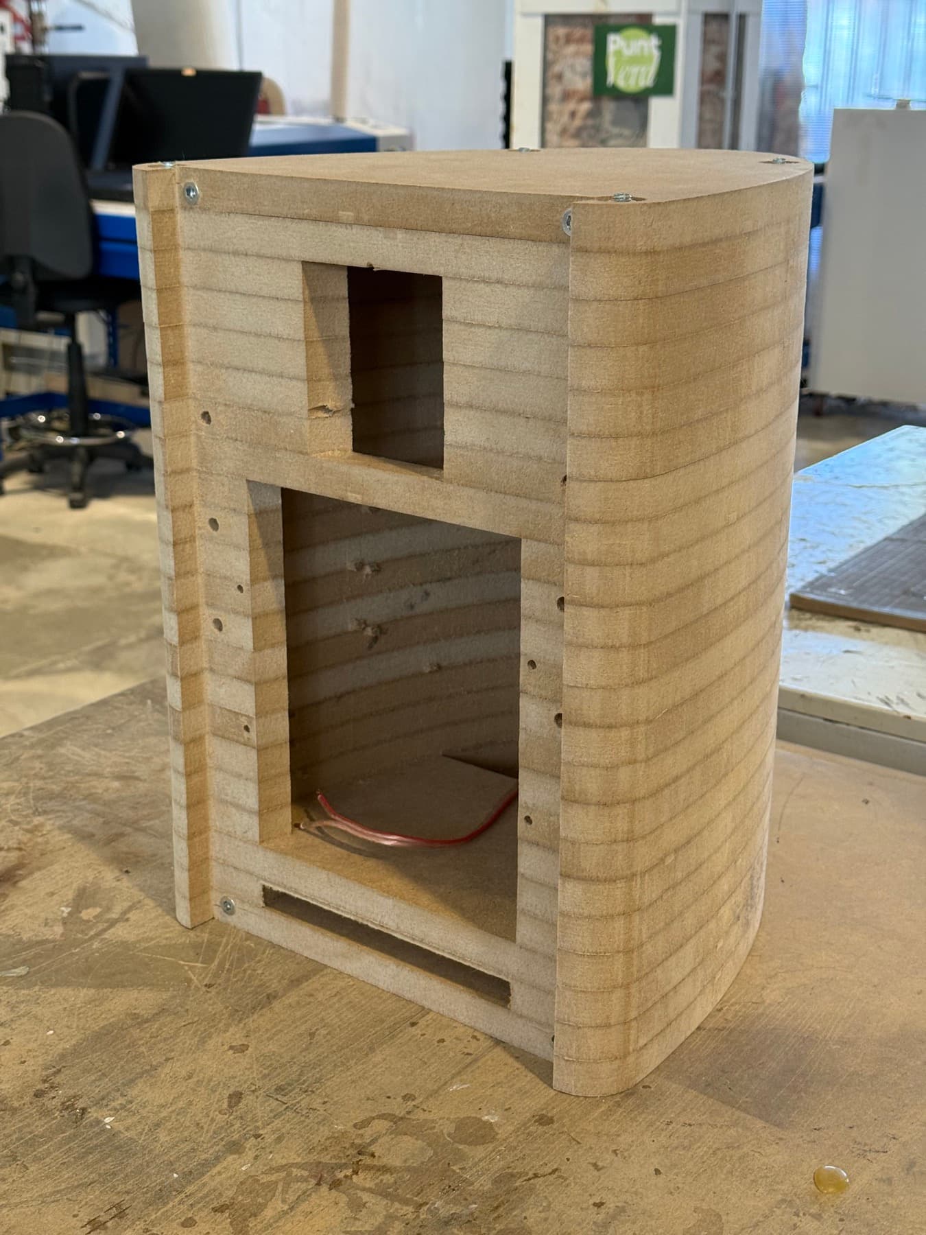
Process photographThe cabinet stacked and compressed, before the baffle is glued on. 05
The crossover
The passive crossover is hand-assembled on a board shaped like the cabinet. Every component is measured before soldering; the woofer coil, for instance, arrived with a higher series resistance than planned and was noted as an open point.
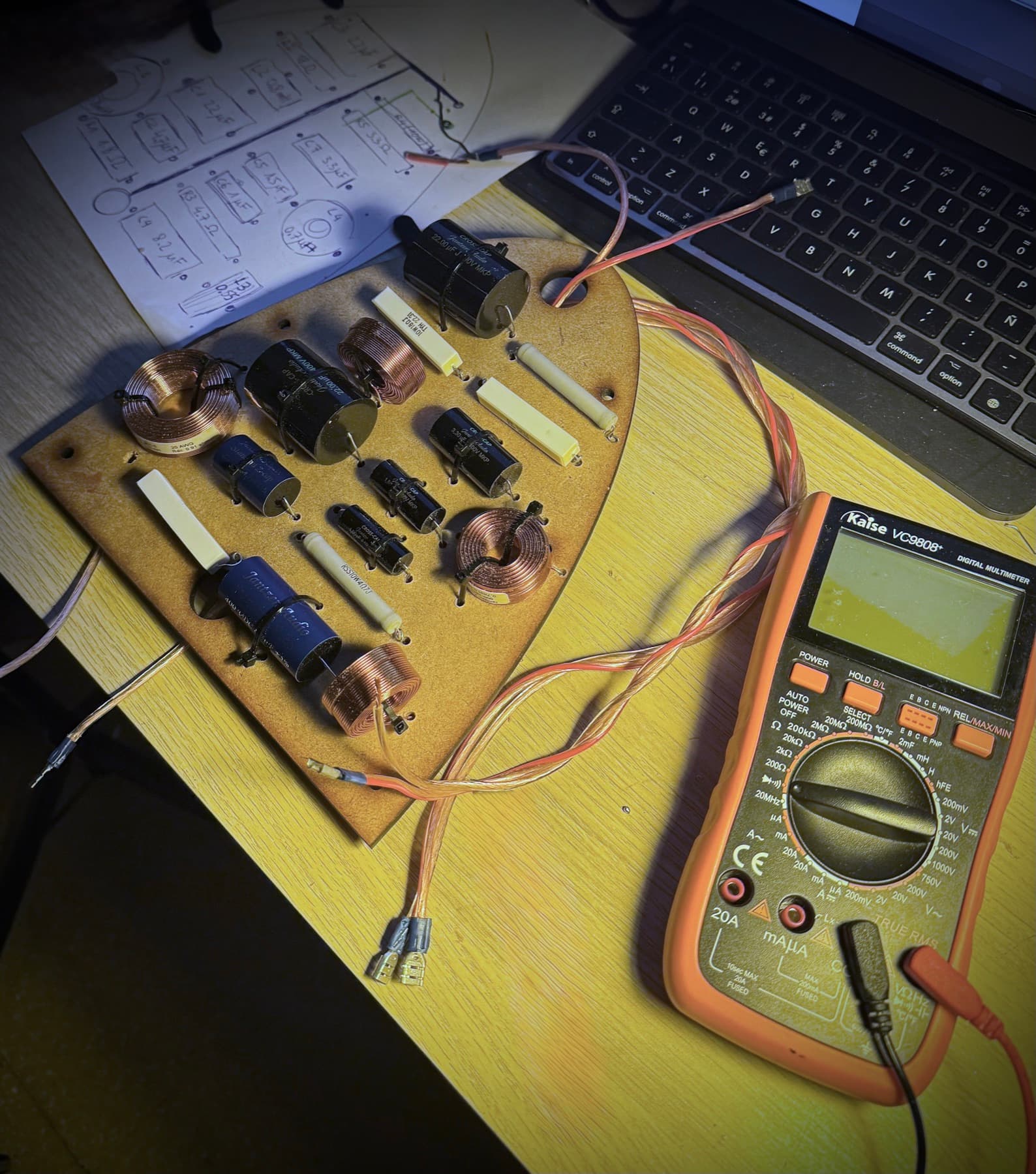
Process photographThe crossover assembled on its board, with the multimeter beside it. 06
The measurements
First at home, with a calibrated microphone at 1 m, to guide the crossover tuning. Then, on 8 October 2026, in Beyma's semi-anechoic chamber: on-axis and 30° response, impedance and distortion at three levels. Those are the data published on the product page.
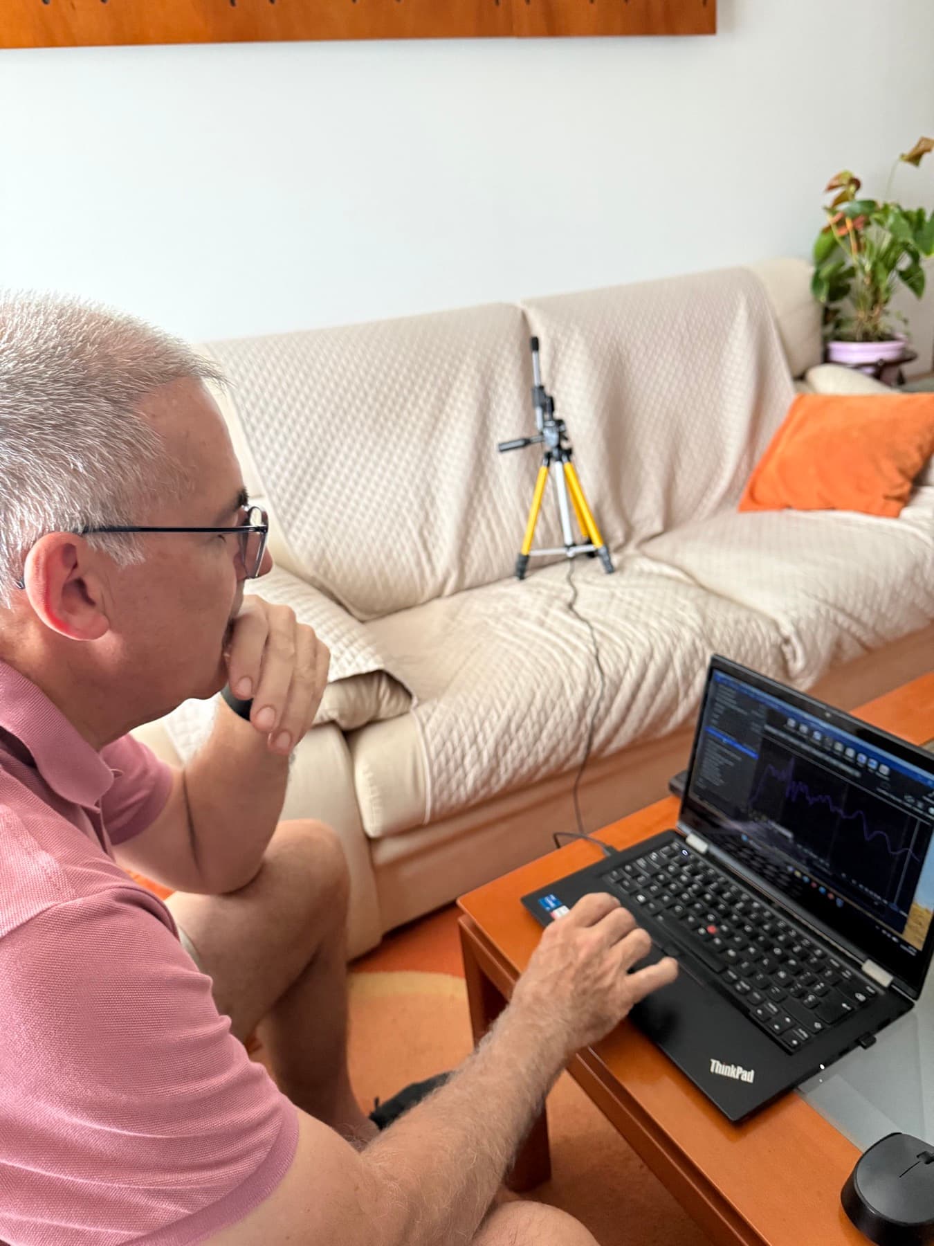
Process photographPreliminary in-room measurement, microphone on a tripod at 1 m. 07
The listening
The prototype is listened to next to known speakers, with the same electronics and the same music, to place what the measurements do not tell. Documented comparative listening and the assembly pilot with an outside person are the next steps.
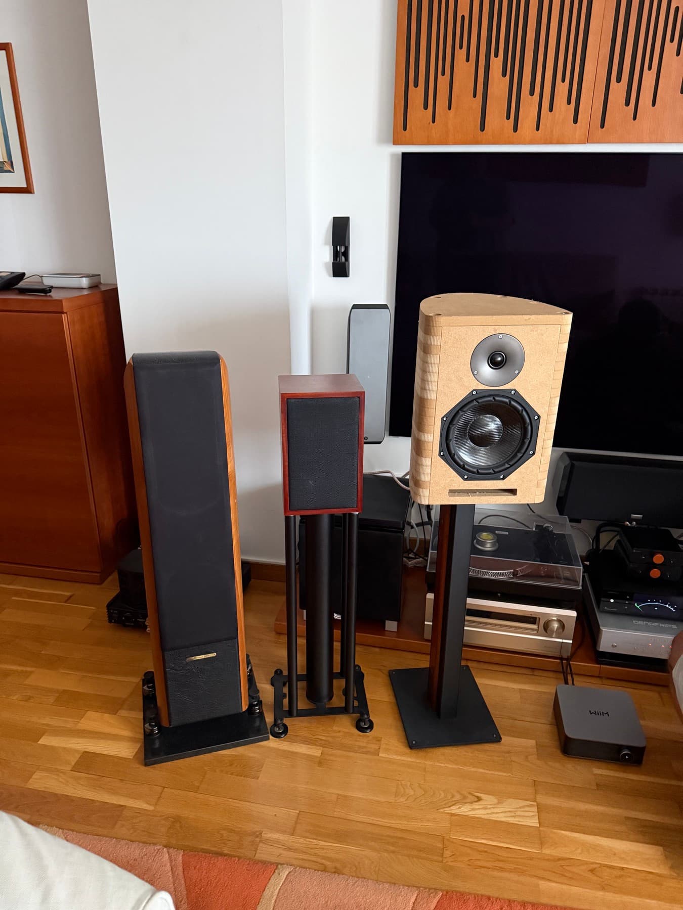
Process photographThe MDF prototype next to two reference speakers in the listening room.