OPUS I / COMPONENTS
Two drivers working as one.
Opus I combines an 8-inch Beyma bass/midrange driver with a Beyma dome tweeter. The passive crossover determines how the two drivers work together. Choosing good components is only part of the task; what matters is how they perform as a system.
8" low-frequency transducer (woofer) · series NMF (near/mid field)
Beyma 8NMFW
Acústica Beyma S.L. · Preliminary Data Sheet (05/22)
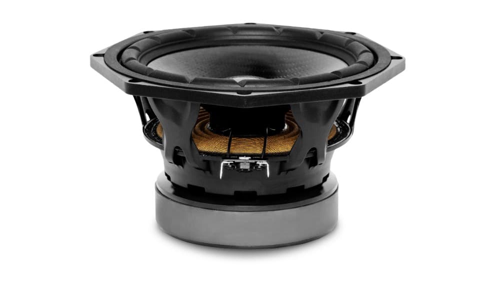
Key specifications
- Nominal diameter
- 200 mm
- Nominal impedanceZn
- 8 Ω
- Sensitivity 2.83 V / 1 m
- 90 dB
- AES power handling
- 200 W
- Usable frequency response
- 30–2,500 Hz
- Resonance frequencyFs
- 37 Hz
- Linear excursionXmax
- 9 mm
- Cone and dust cap
- carbon fibre (cone and dust cap)
- Net weight
- 3.7 kg
Role in the system
- Range
- It covers bass and midrange, from the reflex port up to the crossover region.
- Filter
- 4-element low-pass (L1, C1∥C2+R1, L2, C3+R2)
1" dome tweeter · series NMF
Beyma T25M
Acústica Beyma S.L. · Preliminary Data Sheet (05/22)
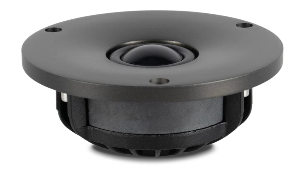
Key specifications
- Nominal diameter
- 25.4 mm
- Nominal impedanceZn
- 4 Ω
- Sensitivity 2.83 V / 1 m
- 88 dB
- AES power handling
- 20 W
- Usable frequency response
- 1,500–30,000 Hz
- Resonance frequencyFs
- 600 Hz
- Dome
- reinforced aluminium–magnesium alloy
- Net weight
- 0.6 kg
Role in the system
- Range
- It covers the treble, above the crossover region.
- Filter
- 2nd-order high-pass (C4, L3) + series trap (L4, C5, C6, R3) + L-pad with shelving (R5∥C7, R4)
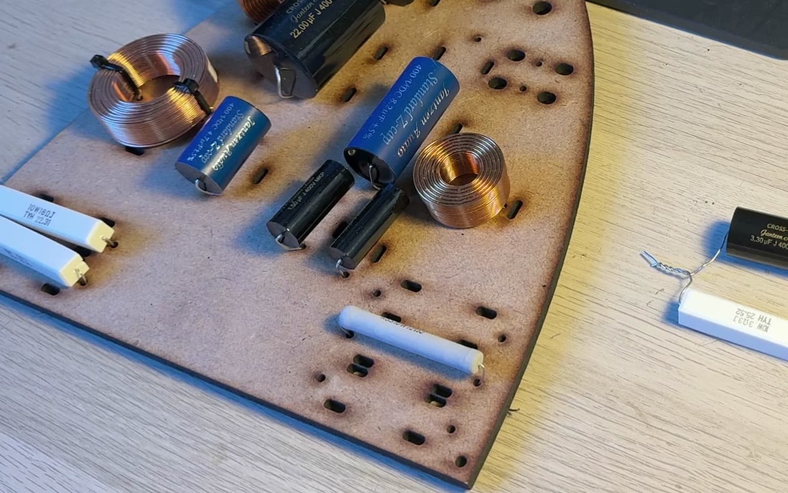
Two-way passive crossover · 16 components
The difference lies in integration.
The technical starting point was a combination of drivers and a crossover topology published by Beyma. The development of Opus I has addressed the Lira enclosure, its geometry, manufacturing and the physical implementation of the crossover, alongside other integration decisions. Acknowledging this starting point is part of how we explain our work.
The crossover is the ‘Passive crossover design’ that Beyma publishes for its recommended 8NMF + T-25M enclosure (the same 16 values and the same topology, with L4 heading the trap to ground). Opus I fits L1 = 1.5 mH instead of 1.58 mH.
Bass · LF
LF+ → L1 → [C1∥C2 + R1 to ground] → L2 → [C3 + R2 to ground] → 8NMFW+
Treble · HF
HF+ → C4 → [L3 to ground] · [L4+C5+C6+R3 trap to ground] → (R5∥C7) → [R4 to ground] → T25M+
L11.5 mH (design 1.58 mH)Bass · LF
Air-core inductorDayton Audio · AC201 (air core, perfect layer) · AC201-5
DCR 0.91 Ω · 20 AWG · air core · ±5 % · Ø46 × 14 mmOpus I fits the 1.5 mH Dayton AC201-5, not the 1.58 mH of Beyma's design (−5.1 %). Dayton rates it at 200 W RMS. Dayton does not publish the inner diameter: we estimate it at ~10 mm by calculation.
It is the first series inductor of the woofer low-pass, between the LF+ input and node A.
L20.8 mHBass · LF
Air-core inductorJantzen Audio · Air Core Wire Coil · 000-1394
DCR 0.62 Ω · 20 AWG · air core · ±3 % · Ø37 × 15 mm
It is the second series inductor of the low-pass, between node A and the woofer's + terminal (node B).
L30.55 mHTreble · HF
Air-core inductorJantzen Audio · Air Core Wire Coil · 000-1846
DCR 0.51 Ω · 20 AWG · air core · ±3 % · Ø34 × 15 mm
It shunts node N1 to ground and is the second element of the 2nd-order high-pass.
L40.7 mHTreble · HF
Air-core inductorJantzen Audio · Air Core Wire Coil · 000-1855
DCR 0.58 Ω · 20 AWG · air core · ±3 % · Ø35 × 15 mmDCR: Jantzen's website gives 0.58 Ω; the project BOM says 0.57 Ω.
It heads the L4–C5–C6–R3 series resonant trap, hung to ground from node N1 (after C4). L4 is not in series with the signal.f0 = 1/(2π√(0.7 mH·0.6 µF)) ≈ 7.77 kHz
C122 µFBass · LF
CapacitorJantzen Audio · Cross Cap · 001-0272
MKP · metallised polypropylene film (Zn/Al) · 400 VDC / 250 VAC · ±5 % · Ø34 × 44 mm
Together with C2 (in parallel, 26.7 µF) and R1 it forms the shunt branch to ground at node A, the second element of the low-pass. The project documentation calls it an impedance-correction network.f_LC with actual L1 = 1/(2π√(1.5 mH·26.7 µF)) ≈ 795 Hz
C24.7 µFBass · LF
CapacitorJantzen Audio · Standard Z-Cap · 001-0434
MKP · metallised polypropylene film (Al) · 400 VDC / 250 VAC · ±5 % · Ø20 × 32 mmThe BOM says ‘Cross-Cap’, but 001-0434 is a Standard Z-Cap (Jantzen and SoundImports). SoundImports gives 20 × 31 mm. Standard Z-Cap: tinned OFC copper leads, self-inductance < 15 nH.
It sits in parallel with C1 (22 + 4.7 = 26.7 µF) and completes the capacitance of the shunt branch at node A.
C322 µFBass · LF
CapacitorJantzen Audio · Cross Cap · 001-0272
MKP · metallised polypropylene film (Zn/Al) · 400 VDC / 250 VAC · ±5 % · Ø34 × 44 mm
It forms a series RC branch (C3 + R2) to ground across the woofer terminals (node B): the last shunt element of the low-pass, which compensates the woofer's rising impedance. The project documentation calls it a ‘notch’; without inductance it is not a resonant circuit.f = 1/(2π·18 Ω·22 µF) ≈ 402 Hz; f_LC with L2 = 1/(2π√(0.8 mH·22 µF)) ≈ 1.20 kHz
C48.2 µFTreble · HF
CapacitorJantzen Audio · Standard Z-Cap · 001-0443
MKP · metallised polypropylene film (Al) · 400 VDC / 250 VAC · ±5 % · Ø20 × 47 mmThe BOM says ‘Cross-Cap’, but 001-0443 is a Standard Z-Cap.
It is the series input capacitor of the tweeter's 2nd-order high-pass (HF+ → node N1).f_LC with L3 = 1/(2π√(0.55 mH·8.2 µF)) ≈ 2.37 kHz
C51.5 µFTreble · HF
CapacitorJantzen Audio · Cross Cap · 001-0236
MKP · metallised polypropylene film (Zn/Al) · 400 VDC / 250 VAC · ±5 % · Ø14 × 31 mm
It is a series-trap capacitor, in series with C6 (1.5 µF in series with 1 µF = 0.6 µF).
C61 µFTreble · HF
CapacitorJantzen Audio · Cross Cap · 001-0230
MKP · metallised polypropylene film (Zn/Al) · 400 VDC / 250 VAC · ±5 % · Ø11 × 31 mm
It is a series-trap capacitor, in series with C5.
C73.3 µFTreble · HF
CapacitorJantzen Audio · Cross Cap · 001-0242
MKP · metallised polypropylene film (Zn/Al) · 400 VDC / 250 VAC · ±5 % · Ø18 × 36 mm
It sits in parallel with R5 and bypasses it at high frequencies (L-pad shelving).
R11.8 ΩBass · LF
ResistorJantzen Audio · Ceramic · 002-0748
10 W · wirewound (CuNi wire), ceramic housing · ±5 % · Ø10 × 48 mmThe BOM says ‘Superes’, but 002-0748 belongs to the Ceramic series (Jantzen; SoundImports sells it as ‘Ceramic Resistor’). It has a square 10 × 10 mm section. Jantzen does not publish the parasitic inductance.
It is the series resistor of the C1∥C2 branch to ground. It damps the L1–C section and makes it resistive above f = 1/(2π·R1·26.7 µF).f = 1/(2π·1.8 Ω·26.7 µF) ≈ 3.3 kHz
R218 ΩBass · LF
ResistorJantzen Audio · Ceramic · 002-0811
10 W · wirewound (CuNi wire), ceramic housing · ±5 % · Ø10 × 48 mmThe BOM says ‘Superes’; it belongs to the Ceramic series. It has a 10 × 10 mm section. Jantzen does not publish the parasitic inductance.
It is in series with C3 in the branch to ground at node B; above ≈ 400 Hz the branch behaves as 18 Ω in parallel with the woofer.
R34.7 ΩTreble · HF
ResistorJantzen Audio · MOX · 002-0451
10 W · metal oxide film (Sb-doped SnO₂), flame-retardant coating · ±5 % · Ø8.5 × 53 mmThe BOM says ‘Superes’; 002-0451 belongs to the MOX series. Jantzen does not publish the parasitic inductance.
It is the series-trap resistor and sets the depth and width of the attenuation; at resonance the branch equals R3 + DCR(L4) ≈ 5.3 Ω.Unloaded branch Q = √(L/C)/R = √(0.7 mH/0.6 µF)/5.28 Ω ≈ 6.5
R412 ΩTreble · HF
ResistorJantzen Audio · MOX · 002-0478
10 W · metal oxide film (Sb-doped SnO₂), flame-retardant coating · ±5 % · Ø8.5 × 53 mmThe BOM says ‘Superes’; 002-0478 belongs to the MOX series. Jantzen does not publish the parasitic inductance.
It is the L-pad's branch to ground, in parallel with the tweeter (node N2).Resistive L-pad attenuation: 20·log[(R4∥Zt)/(R5 + R4∥Zt)] = −6.4 dB with Zt = 4 Ω; −7.4 dB with Zt = 3.1 Ω
R53.3 ΩTreble · HF
ResistorJantzen Audio · Ceramic · 002-0766
10 W · wirewound (CuNi wire), ceramic housing · ±5 % · Ø10 × 48 mmThe BOM says ‘Superes’; it belongs to the Ceramic series. It has a 10 × 10 mm section. Jantzen does not publish the parasitic inductance.
It is the L-pad's series arm (N1 → N2). With C7 in parallel it forms a shelf: the attenuation decreases at the top end.Xc7 = R5 at f = 1/(2π·3.3 Ω·3.3 µF) ≈ 14.6 kHz
Electrical validation
Electrical model (woofer with |Z| measured in the enclosure, tweeter as a 3.1–4 Ω resistance): maximum |Zin| ≈ 18.6–18.9 Ω at ≈ 1.45 kHz and minimum ≈ 3.5 Ω at ≈ 8.1 kHz. Beyma measured 17 Ω at 1.4 kHz and 3.9 Ω at 8 kHz (measurement at Beyma, 08/10/2026): the topology and the values are consistent with the measurement.