
OPUS I / THE PROCESS
Every form begins with a decision.
Designing a loudspeaker means asking questions, developing answers and putting them to the test. The development of Opus I brings together drawings, digital models, machined parts, assembly, listening and measurement. This is the journey that has shaped our first creation.
01
From drawing to model.
Digital design allowed us to develop the enclosure's outline while examining its dimensions, internal cut-outs, bracing and suitability for machining. Each revision took a design decision from the drawing into three dimensions.
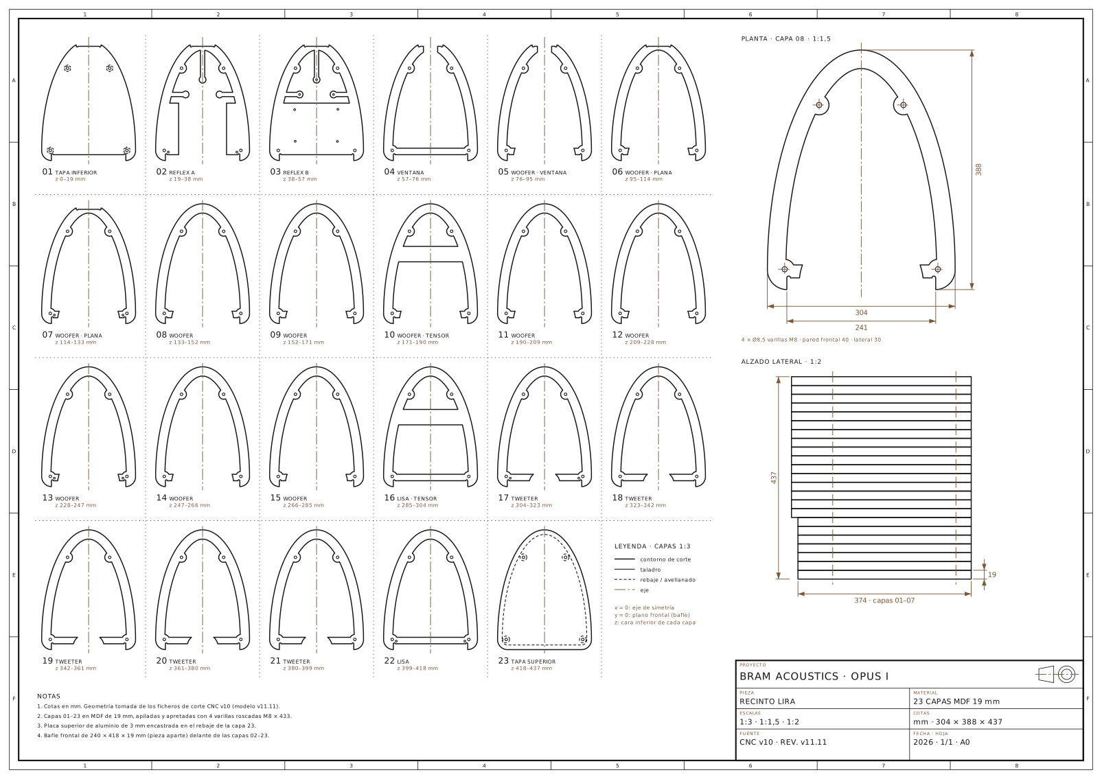
Geometric diagram · Layer profiles of design v11 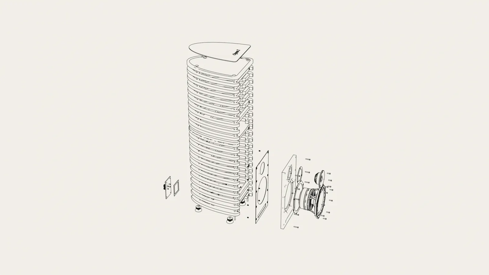
Geometric diagram · Exploded view of design v11
02
From geometry to material.
CNC machining turns each profile into a physical part. But the machine does not decide what should be made. It follows geometry that has already been considered, drawn and revised.
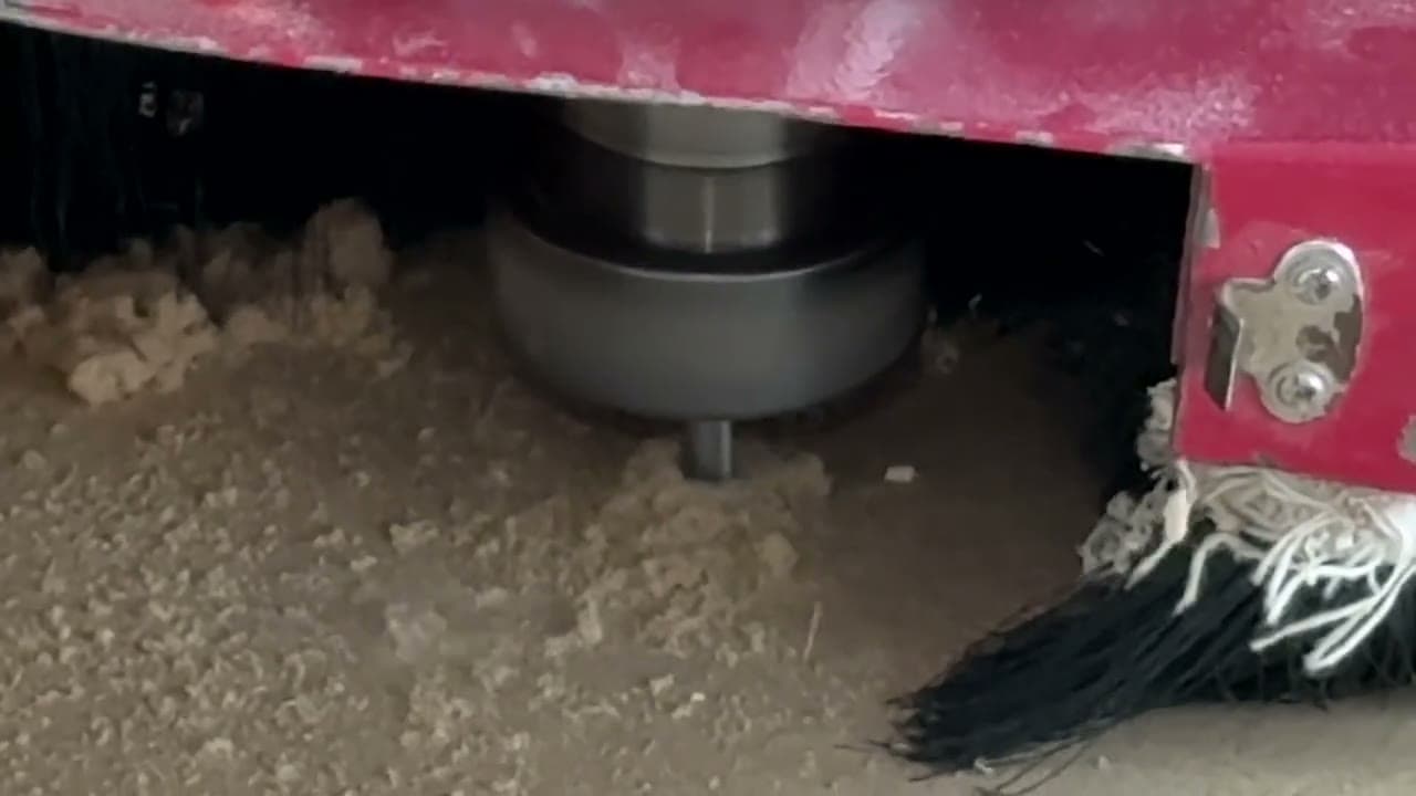
Process photograph · CNC machining · Credit: Nord Taller 03
Precision lies in the joints.
Individual layers become a complete enclosure. Alignment, fit and the way the parts are joined determine how faithfully the physical object follows the design. Assembly also provides an opportunity to review what we have learnt.
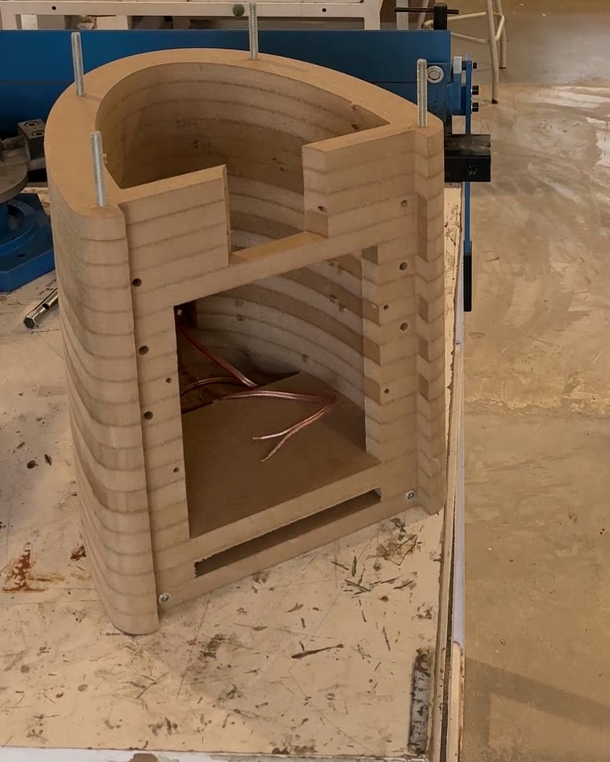
Process photograph · Layers stacked in the workshop 04
Making every element work together.
Driver selection and the physical construction of the passive crossover are integrated with the enclosure volume, front baffle and internal geometry. In a loudspeaker, the result depends on how the parts interact, rather than on a component list considered in isolation.
The crossover is based on a topology published by Beyma for this driver combination; the Opus I mounting board is our own design.
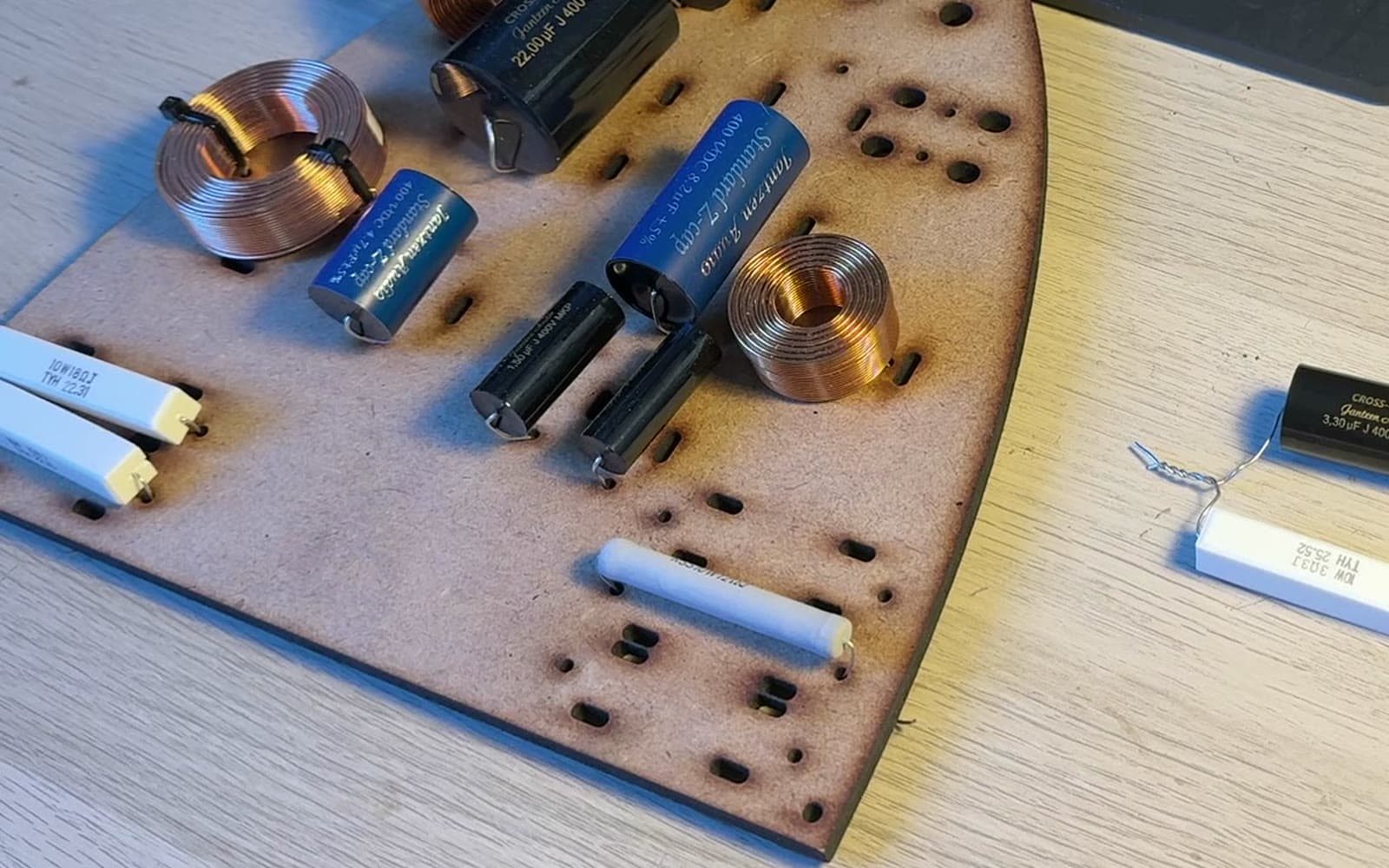
Process photograph · Crossover board 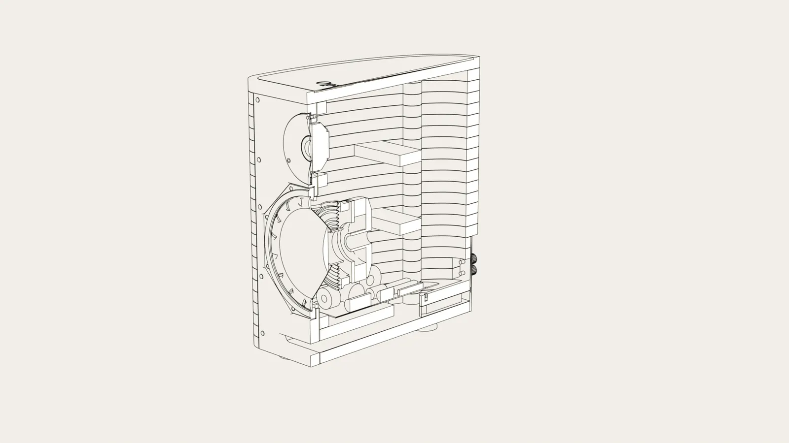
Geometric diagram · Section of design v11
05
Explore the measurementsMeasurements provide questions and answers.
On 8 October 2026, one unit of prototype v11 was tested in Beyma's semi-anechoic chamber. The tests examined frequency response, impedance and distortion, together with measurements at different input voltages and at 30° horizontally.
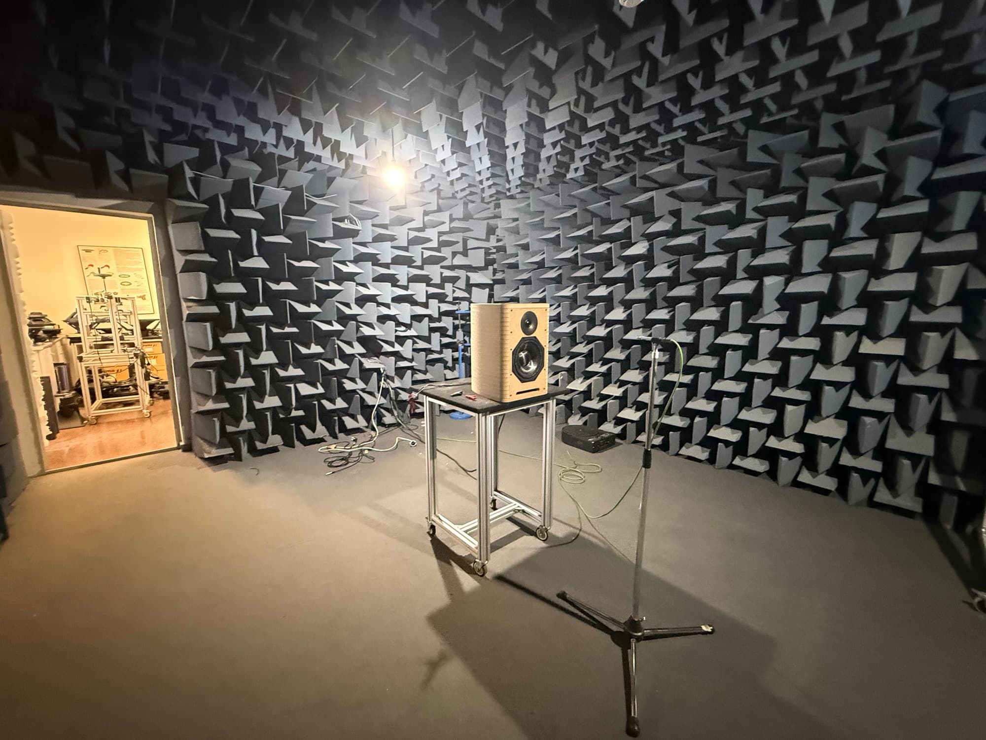
Process photograph · Beyma semi-anechoic chamber, 08/10/2026 · Credit: Beyma 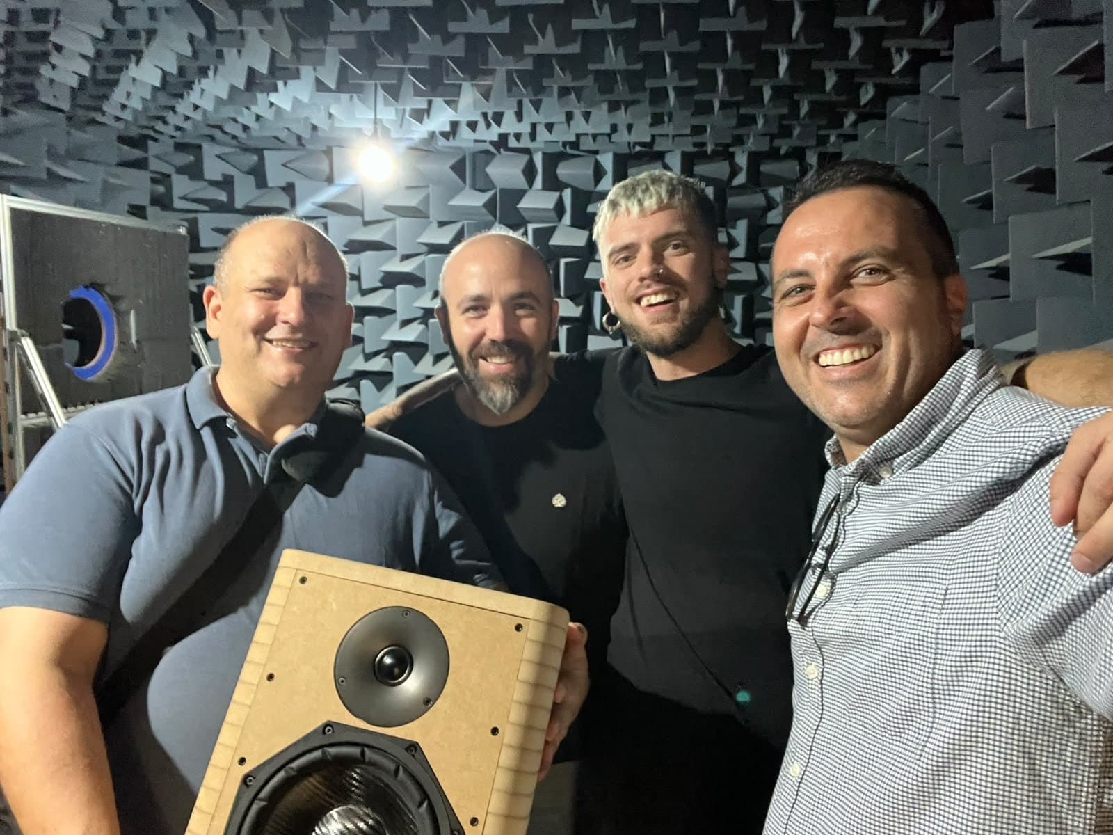
Process photograph · Team with the prototype inside Beyma's chamber
An independent project also acknowledges the work of others.
BRAM takes responsibility for the design and development of its products. Our work draws on components, technical knowledge and manufacturing expertise from specialist partners and workshops. Acknowledging their contributions is part of our approach.
- Design and project direction: Josep Maria Marimon / BRAM Acoustics.
- Drivers and technical collaboration: Beyma.
- Enclosure machining: Nord Taller.
- Crossover components: Jantzen and Dayton.
The finished result does not erase the journey.
Opus I is the first outcome of an approach we intend to keep developing. Designing with purpose also means being able to explain how we arrived at each decision.
Discover Opus I