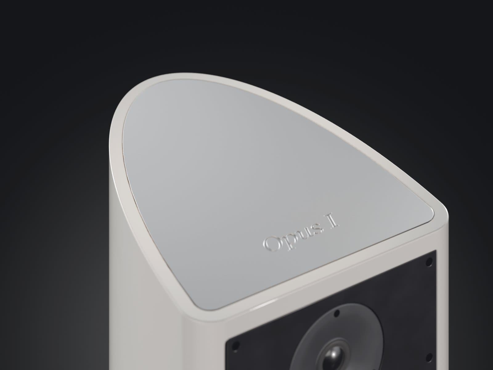
OPUS I / LIRA ARCHITECTURE
A form that begins within.
The Lira architecture was not conceived as a new exterior for a conventional enclosure. Its geometry was developed alongside the internal layout, mechanical structure and method used to manufacture each element.
Curves outside. Decisions within.
The acoustic front baffle retains a width of 240 mm. Behind it, the enclosure develops a curved geometry without pairs of parallel internal walls. This form allows the internal volume and structure to be organised without arbitrarily changing the proportions of the front baffle.
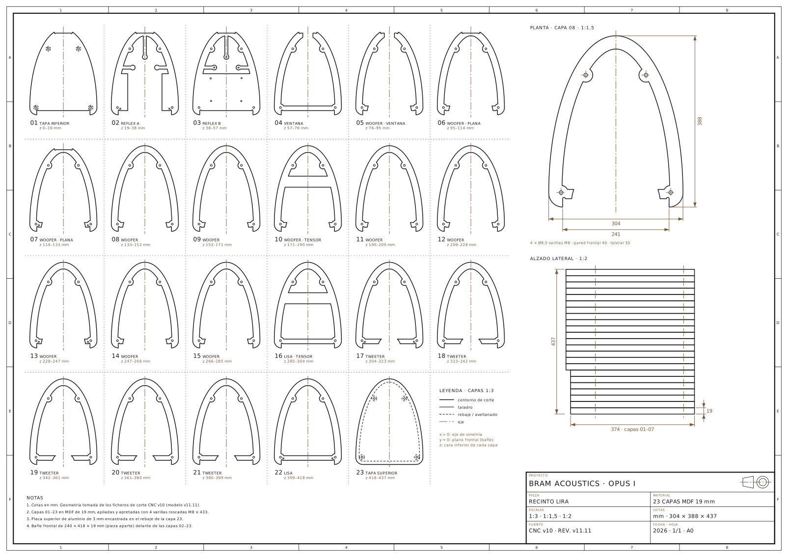
Front baffle width: 240 mm. External dimensions of design v11: 304 × 388 × 437 mm.
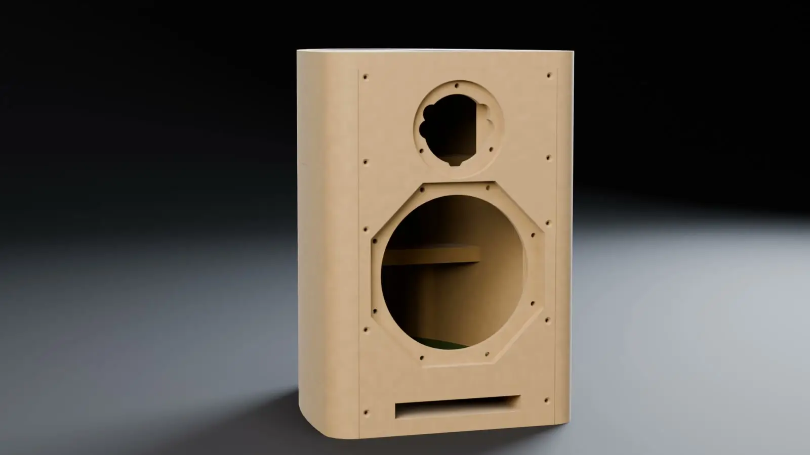
3D visualisation based on the Opus I design.
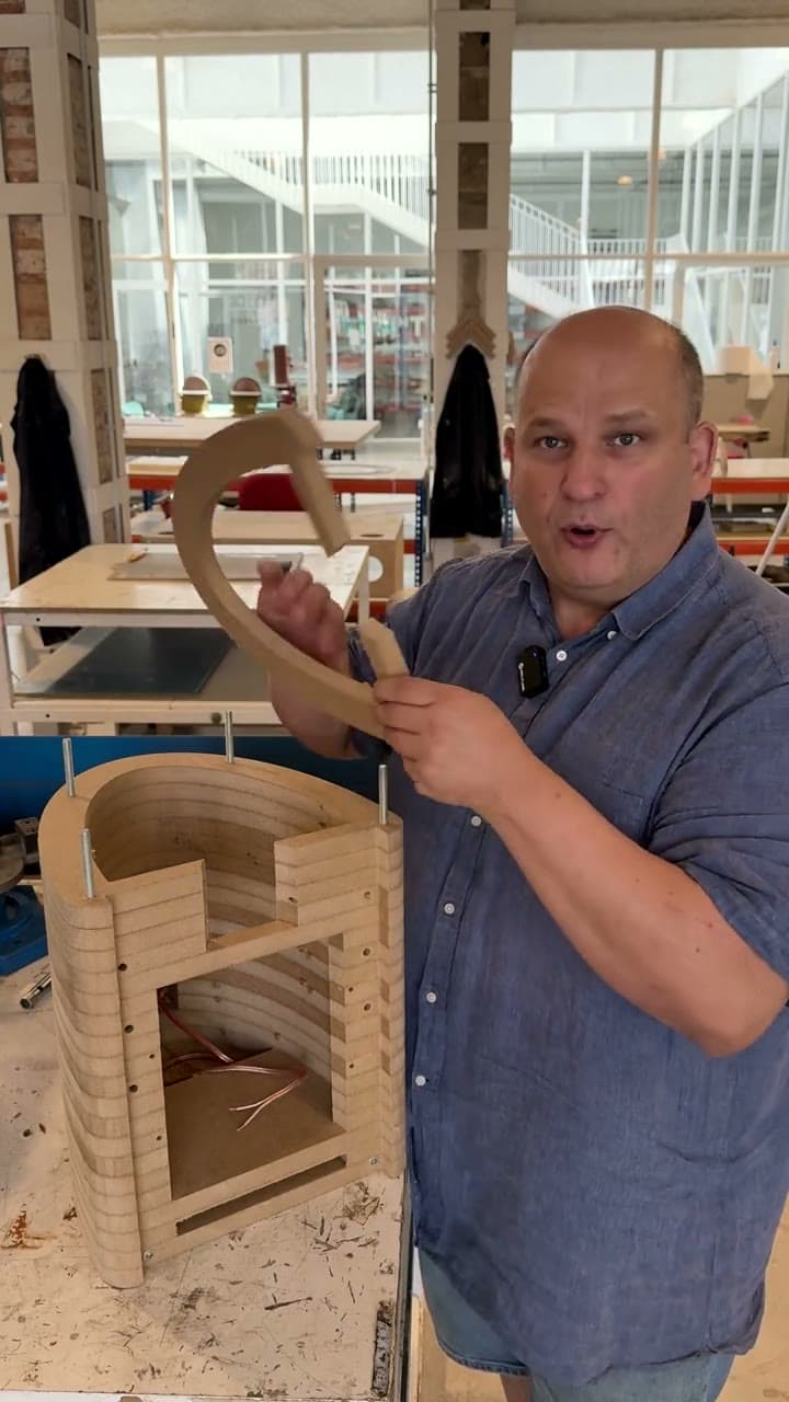
The enclosure body is constructed from 23 layers of 19 mm MDF, machined by CNC. Each layer has a defined position and purpose within the structure. Stacking the profiles makes it possible to create curves, internal cut-outs and bracing directly from the digital model.
Construction is also about control.
Variable wall thicknesses, internal bracing and mechanical connections form a structure designed to limit panel vibrations. The front baffle is a separate, removable element, while threaded rods secure the layers of the enclosure body.
MAINTENANCE AND EVOLUTION
An architecture designed to be opened again.
We designed Lira as a structure that can be opened, worked on and reassembled. Its 23 MDF layers are joined mechanically, without gluing the body. Every joint is designed to give access to the interior and to keep the loudspeaker serviceable over time.
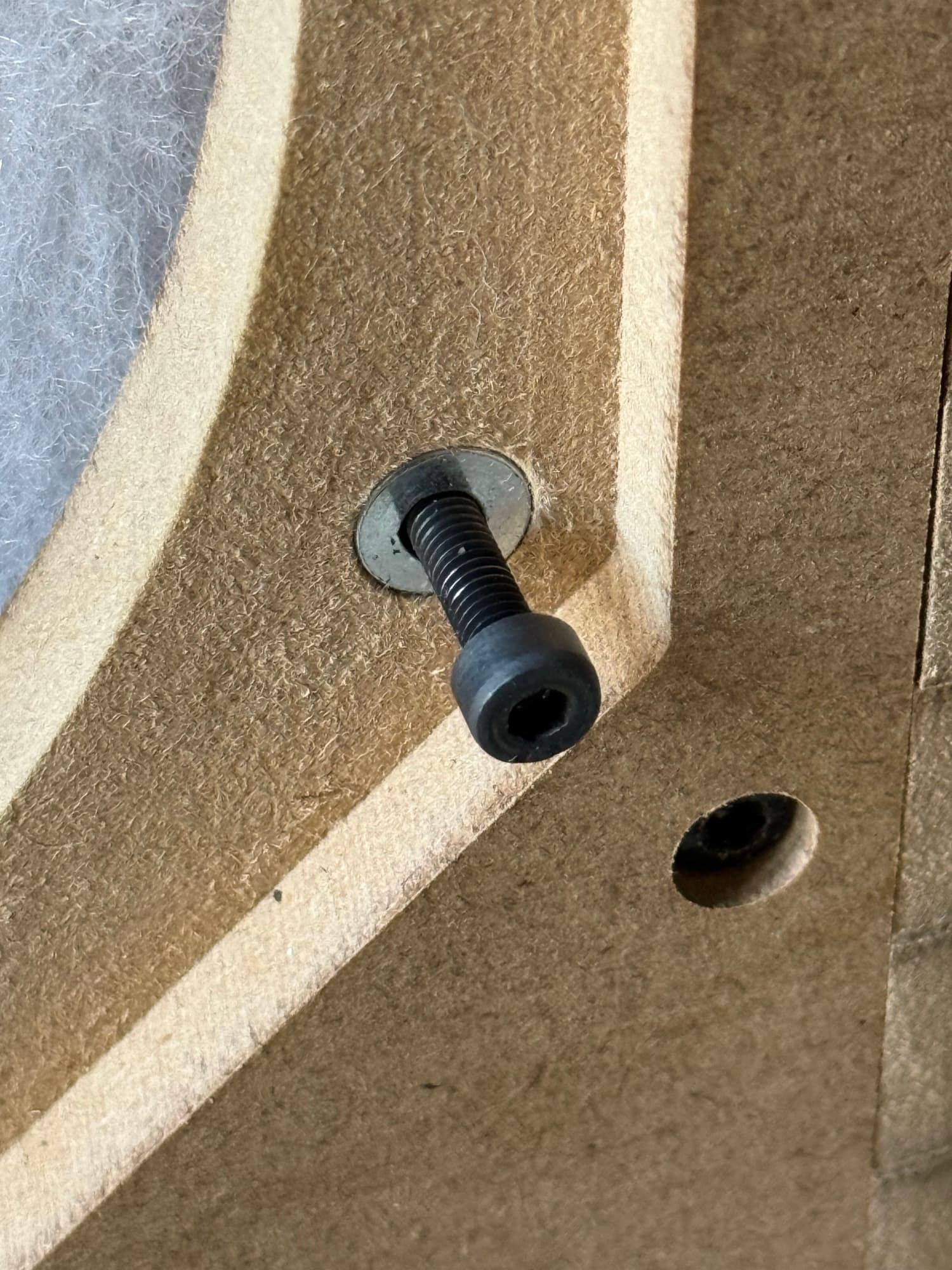
The bolts work on metal parts, never directly on the wood. This lets us take the parts apart and put them back together as often as necessary, using the right tools and following the assembly procedure.
- A body that comes apart.
- Four M8 threaded rods hold the 23 layers together with nuts. We use medium-strength Loctite 243 threadlocker, which allows the joints to be undone with tools.
- An independent baffle.
- Ten M4 bolts fix it to cross-dowel nuts housed in the enclosure. A butyl cord provides the seal. The baffle can be replaced with another with different cut-outs or finishes.
- Threads on metal.
- The drivers and the crossover are fixed with M4 threaded inserts. The joints prevent wear on the wood threads during assembly work.
- One key.
- All the bolts on the baffle and the drivers use a 3 mm Allen key.
- An adaptable geometry.
- Replacing a layer changes the internal volume or the port geometry. Adding layers increases the height of the enclosure, using rods of the corresponding length.
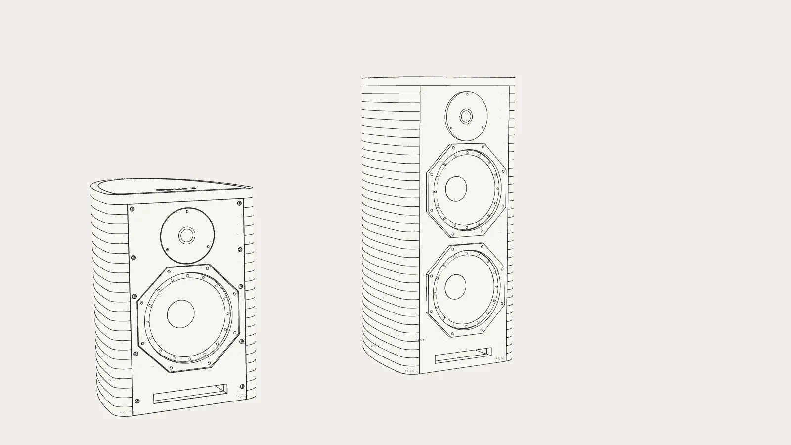
3D visualisation · Concept study, not a product: a floorstander one and a half times taller, with the same layers, two adjacent woofers and one tweeter at the top
This architecture makes it easier to repair and replace components, update the crossover and adapt the baffle. It also lets us study configurations with a larger volume or an additional way, even a three-way floorstander on the same constructive base. Each new configuration would require its own development and acoustic tuning.
Bass reproduction needs space and a defined path.
The enclosure incorporates a front-firing bass-reflex port formed within its lower layers. Port design is part of the cabinet geometry: internal volume, cross-section, length and the shape of its opening are considered as elements of a single system.
Port in design v11: 155 × 19 mm cross-section and 186 mm length.
The precision of the file. The care of the workshop.
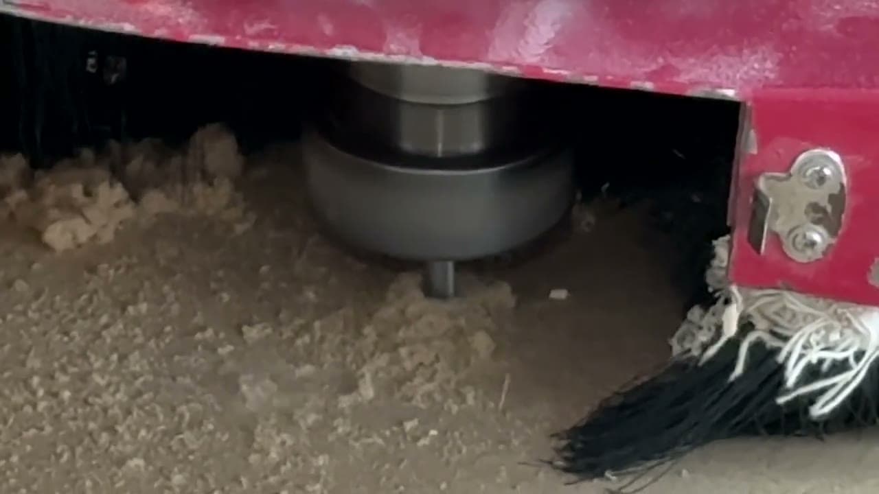
CNC machines translate the digital model into physical parts. The workshop stages that follow are just as important as machining: preparing surfaces, checking fit, finishing the port opening and assembling the enclosure with care.
Explore the manufacturing process